All posts

In the event of a short circuit, the only thing limiting the current is the impedance of the path back to the source. The magnitude of that current must be determined at every point where equipment is installed, so that every overcurrent protective device and every assembly is correctly rated for the fault condition.
Underrating equipment produces an unsafe installation, but overrating it adds cost without benefit. Calculating the available fault current at the point of application avoids both.
Kopperfield performs this calculation.
On this page
- What is short circuit current?
- Short circuit current vs. fault current vs. available fault current
- What determines available short circuit current?
- Does short circuit current increase or decrease downstream?
- How do you calculate short circuit current?
- Short circuit current calculation example
- What do you do with the short circuit current value?
- Short circuit current calculator
- FAQ
What is short circuit current?
Short circuit current is the current that flows through a circuit when a fault bypasses the load and establishes a path of very low impedance. With almost nothing left to hold it back, that current runs many times higher than the circuit's normal load.
It is a property of the system, not of the connected load. A 20 A branch circuit supplied from a large service can have tens of thousands of amperes available at its breaker. Load current is not an indicator of available short circuit current.
It is established by calculation rather than measurement. The value is derived from source impedance and conductor impedance before a fault occurs. Utilities publish a value at the service point; all values downstream of that point are determined by the designer or installer. The point-to-point method is the industry-accepted way to establish those downstream values, and it is sufficient for most commercial and residential work. Kopperfield's available fault current calculator reports the value at every point from the transformer to the panel.
Short circuit current vs. fault current vs. available fault current
| Term | What it refers to |
|---|---|
| Short circuit current | Current flowing during a fault, used as the general term |
| Fault current | The same quantity, somewhat broader, encompassing ground faults and arcing faults |
| Available fault current (AFC) | The maximum fault current the system can deliver at a specific point |
| Available short-circuit current | Synonym for available fault current, the phrasing used in NEC 110.10 |
| Short-circuit current rating (SCCR) | A withstand rating for a whole assembly, governed by the weakest component inside it |
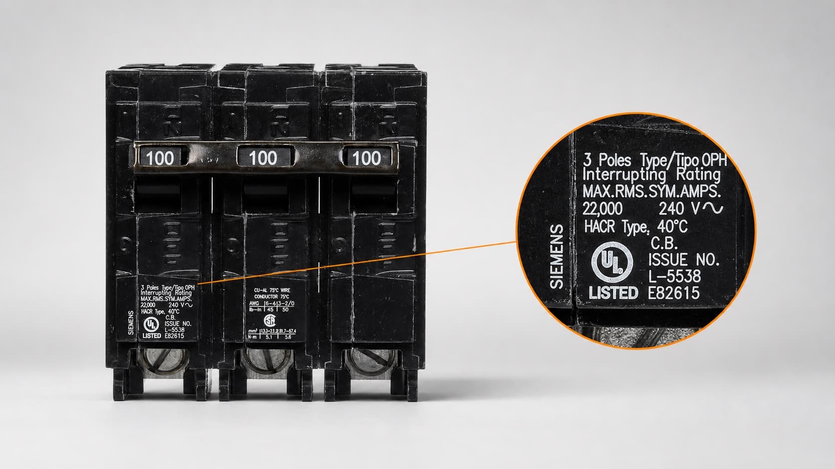
SCCR is the most frequently misapplied term of the group. It expresses the fault current an entire assembly can withstand, and the rating accounts for everything inside the enclosure rather than the main breaker alone. Terminal blocks, disconnects, contactors, and overload relays each carry their own rating, and the lowest one governs the assembly. That figure is what gets evaluated against the available short circuit current at the point of installation. The interrupting rating (AIC) of a breaker or fuse is compared the same way, but it rates that one device rather than the assembly around it. SCCR vs. AIC rating addresses both ratings in detail.
For documentation, "available fault current" is the preferred term. It is the language used by the NEC, and it is the term an inspector expects to find on a service label.
What determines available short circuit current?
Four things set the available short circuit current: the size of the source transformer, its nameplate impedance, the length of the conductors between the source and the point of fault, and the size, material, and raceway of those conductors. A fifth, connected motor load, can add to it. They are listed below in approximate order of influence.
| Input | Effect |
|---|---|
| Source transformer size | A larger transformer delivers more fault current. This factor is dominant at the service. |
| Transformer impedance (%Z) | Lower impedance delivers more fault current. A 2% unit delivers approximately twice the current of an equivalent 4% unit. |
| Conductor length | Each foot of conductor adds impedance and reduces the available current. This is the principal variable downstream of the service. |
| Conductor size, material, and raceway | Larger conductors and parallel runs present less impedance and pass more fault current. Copper passes more current than aluminum of the same size. |
| Connected motor load | Running motors feed current into a fault for the first few cycles. Four times their full-load amperes is the common practical estimate, with four to six the accepted range. Usually too small to matter on branch and feeder work, but worth adding where a large motor load sits close to the equipment. |
Shortening a service conductor run increases the available short circuit current at the service equipment. A routing change made after the calculation is complete can raise the value beyond both the rating of the specified equipment and the figure stated on the field marking, and such changes are not consistently reported back to the designer. Where conductor length or routing is revised after the study is issued, the calculation should be reperformed and the marking corrected.
Does short circuit current increase or decrease downstream?
In a radial system fed from one source, short circuit current decreases downstream, and the maximum occurs at the transformer secondary, because each foot of conductor between the transformer and the point of fault adds impedance. Connected motors, a second transformer in parallel, and on-site generation are the exceptions, and each of them can raise the value at a point below the service.
Equipment that would be inadequate at the service can be entirely suitable further downstream. A single building-wide value is therefore insufficient. A value is required at each point of equipment installation: the service and main switchboard, transfer switches, panelboards and load centers, motor control centers and motor starters, disconnects, and the secondary of any downstream transformer.
How do you calculate short circuit current?
Short circuit current is calculated by the point-to-point method, one segment at a time. The value at the source is established from the transformer kVA and nameplate impedance, then reduced across each conductor run according to its length, size, and material.
Step 1: short circuit current at the source
Where the serving utility has provided an available fault current value, or where a meter reading is available, that figure is used directly. A utility-supplied value takes precedence over any calculated estimate.
Where no such value is available, the calculation proceeds from the transformer nameplate using the short circuit current formula below.
Note that the nameplate impedance is multiplied by 0.90 before dividing. The number stamped on a transformer is a design value, not a measurement of the unit in front of you. UL Standard 1561 lets a listed dry-type transformer of 25 kVA or larger come in up to 10 percent either side of it, and transformers built to ANSI standards carry a 7.5 percent tolerance. The real impedance of any given unit sits somewhere in that band.
Lower impedance means higher fault current. Design to the bottom of that band and the equipment is sized for the most current the transformer could deliver. That is the job of the 0.90, and it raises the result about 11 percent.
The calculation assumes an infinite primary source of zero impedance. This maximizes the result, which is the conservative direction.
Two cases need a further adjustment at the transformer terminals: a line-to-neutral fault on a 120/240V center-tapped secondary, and a line-to-line branch of a three-phase system. Each has a published multiplier applied to the terminal value before the run is calculated. Kopperfield's calculator applies both automatically.
Step 2: calculate point to point, over the conductor run
- L is one-way length in feet, not the round trip. The factor of 2 in the single-phase expression accounts for the return path.
- I is the short circuit current at the start of the run.
- C is the conductor constant for the size, material, and raceway in use.
- n is the number of conductors per phase, which accommodates parallel runs.
- V is the voltage across the faulted path. Three-phase and line-to-line runs use the line-to-line voltage; a line-to-neutral run uses the line-to-neutral voltage. On a 120/240V system that is 240V and 120V respectively, and substituting the wrong one is the easiest way to get a run wrong. The line-to-neutral case also assumes the neutral is the same size as the line conductor.
C values are the reciprocal of impedance per foot. They are published as a lookup table by conductor size, material, and raceway, derived from resistance and reactance values in IEEE Std 241-1990 and IEEE Std 242-1986, and cover copper and aluminum in steel and nonmagnetic raceway. Nonmagnetic denotes PVC or aluminum conduit, and steel yields a lower C value because it introduces additional reactance. You can find the reference tables of C values in references like Ugly's Electrical Reference.
Step 3: repeat at each point, over each conductor run
The result becomes the starting current for the next segment. The procedure is repeated at each point where a value is required.
A transformer partway down the system is the exception, and it needs separate handling. It is not an infinite source the way the one at the service was treated: the short circuit current at its secondary is limited by the current actually arriving at its primary, working against its own impedance. It also steps the voltage, so every point past it is calculated at the new secondary voltage. That calculation is outside the scope of this article, though Kopperfield's calculator handles it.
Short circuit current calculation example
The example below calculates short circuit current at three points on a 480V three-phase system: the transformer secondary, a main distribution panel 60 feet away, and a sub-panel a further 120 feet downstream.
System: 750 kVA transformer, 480Y/277V three-phase, 3.5% nameplate impedance. 60 ft of 500 kcmil copper, 3 per phase, in steel conduit to the main distribution panel. 120 ft of 2/0 copper, single run, in steel conduit to a sub-panel.
Short circuit current at the transformer secondary
Conductor run to the main distribution panel. C = 22,185 for 500 kcmil copper in steel conduit; n = 3.
Conductor run to the sub-panel. C = 10,755 for 2/0 copper in steel conduit; n = 1.
| Point | Available short circuit current |
|---|---|
| Transformer secondary | 28,639 A |
| Main distribution panel | 26,199 A |
| Sub-panel | 12,750 A |
The first run reduces the value by 8.5 percent over 60 feet of parallel 500 kcmil conductor. The second reduces it by more than half over 120 feet of 2/0. Conductor size exerts greater influence on the result than length alone would indicate.
The main distribution panel therefore needs equipment rated for at least 26,199 A. In practice that means 42 kAIC gear, because the next standard rating down, 25 kAIC, does not clear the calculated value. The sub-panel is comfortably served by standard 22 kAIC equipment. A 10 kAIC panel at that location would be underrated, a condition not evident from the panel's position 180 feet from the transformer.
What do you do with the short circuit current value?
The calculated value supports three determinations: selecting equipment with adequate interrupting ratings and SCCR, producing the field marking and documentation the NEC requires, and providing the first input to an arc-flash study.
Equipment ratings. Breakers and fuses require an interrupting rating not less than the available fault current under NEC 110.9. Assemblies require an SCCR not less than the available fault current, which NEC 110.10 addresses as a coordination requirement and 408.6 states directly for switchboards, switchgear, and panelboards. Where the available current exceeds the rating, the options are to specify higher-rated equipment, to apply a listed series-rated combination, or to reduce the available current through a higher-impedance transformer or a longer or smaller feeder. How the two ratings differ sets out the comparison.
Field marking and documentation. NEC 110.24 requires service equipment at other than dwelling units to be field-marked with the available fault current and the date of the calculation, and it requires the calculation itself to be documented. The marking alone does not satisfy the section. Since the 2020 edition, 408.6 extends the marking requirement to switchboards, switchgear, and panelboards at other than one- and two-family dwellings. NEC 110.24 label requirements covers the content of the marking and the circumstances requiring recalculation.
Arc-flash analysis. Short circuit current is the first input to an incident-energy calculation under NFPA 70E.
The point-to-point method is appropriate for most commercial and residential work. An engineered short-circuit study, sealed by a professional engineer, is warranted where the system incorporates multiple sources or on-site generation, substantial motor load, medium-voltage distribution, or fault levels sufficiently close to equipment ratings that the margin is material.
Short circuit current calculator
Because the method works point to point, every result is the starting current for the next one. An error upstream, a transposed C value or a mistyped run length, propagates into every point below it, and the results still look plausible, so nothing flags it. The arithmetic is simple, but it has to be right at every step.
Kopperfield's short circuit current calculator accepts a utility-supplied value or a transformer's kVA and nameplate impedance, accommodates each conductor run and item of equipment in the chain, and returns the short circuit current at every point. It covers 120/240V through 600V, single-phase and three-phase, incorporates C values for copper and aluminum, and applies the 0.90 impedance adjustment and the terminal multipliers automatically. Each calculation exports as a branded PDF containing the per-point table and the stated assumptions, and it is retained on the organization's dashboard for subsequent reference.
Two calculations are included free. Unlimited calculations are available with Commercial Pro.
Frequently asked questions
Does a utility-supplied fault current value expire?
The NEC establishes no expiration period. NEC 110.24(B) requires that the available fault current be verified or recalculated, and the field marking corrected, where a modification affects the value at the service. The serving utility can change the value without any modification on the customer side. Reconductoring the primary or replacing a 300 kVA transformer with a 500 kVA unit will both raise the available fault current at the service point. Where a utility letter is several years old and the surrounding distribution system has been upgraded, a current value should be requested before equipment is specified.
The transformer nameplate is illegible. How is the impedance determined?
Request the value from the serving utility first, as a utility-supplied figure takes precedence over any estimate. For customer-owned transformers, the manufacturer can generally supply the impedance from the serial number. Where neither source is available, a published typical impedance for the kVA rating and construction type may be used, selected from the low end of the range: low impedance produces high short circuit current and is therefore the conservative assumption. The value used and its source should be recorded with the calculation.
Does correspondence from the serving utility satisfy the documentation requirement of NEC 110.24?
It establishes the starting value and should be retained, but it does not constitute the calculation. NEC 110.24(A) requires the calculation to be documented and made available to those authorized to design, install, inspect, maintain, or operate the system. A statement of the available fault current at the service point does not establish the values at downstream equipment. The utility correspondence and the per-point calculation together satisfy the requirement.
Does any of this apply to dwelling units?
The field marking required by NEC 110.24 applies at other than dwelling units, so a dwelling unit generally does not require it. Note that 408.6 is narrower: it exempts only one- and two-family dwellings, so panelboards in a multifamily building still need the marking even though 110.24 does not reach them. The comparison against equipment ratings applies regardless of occupancy. Short service conductors supplied from a large pad-mounted transformer can deliver more short circuit current at a residential panel than is commonly assumed.
Is this the same as the short circuit current listed on a photovoltaic module?
No. The short circuit current on a PV datasheet is the current a module produces with its terminals shorted and no load connected, and the value varies with irradiance. It is a module performance rating, used for sizing conductors and overcurrent protective devices on the array. It does not describe the current a fault in the distribution system can deliver.