All posts

Contractors run into different types of electrical diagrams depending on the job. It's not always obvious what each one does, or which one you need.
The drawing you need depends on who is reading it. A plan reviewer checking a permit set, a crew in rough-in, and a controls tech troubleshooting a motor starter each work from a different sheet.
On this page
- What are the main types of electrical diagrams?
- Single line diagram (one line diagram)
- Riser diagram
- Wiring diagram
- Schematic diagram
- Pictorial diagram
- Block diagram
- Floor plan
- Site plan
- Scope of work drawing
- Which diagrams do you need for a permit?
- What symbols are used?
- FAQ
What are the main types of electrical diagrams?
The types of electrical diagrams you will run into most are single line diagrams, riser diagrams, wiring diagrams, schematic diagrams, pictorial diagrams, block diagrams, floor plans, site plans, and scope of work drawings. Each one answers a different question about the same installation.
| Diagram type | What it shows | Typical use |
|---|---|---|
| Single line diagram / one line diagram | Connections between sources and loads, drawn with one line per connection | Permits, service upgrades, EV, solar, battery, generator installs |
| Riser diagram | Connections between sources and loads, laid out according to location. Most commonly, floor by floor, rising up through the building | Multifamily, multi-story, and commercial |
| Wiring diagram | Physical connections between components, close to real layout | Installation, equipment hookup |
| Schematic diagram | How a circuit operates, regardless of physical location | Understanding how a circuit works |
| Pictorial diagram | Components and the wiring between them, labeled so no symbol knowledge is needed. Some use drawings of the actual parts | Training, homeowner explanations |
| Block diagram | Major system parts and how they connect | High-level planning and explaining a system |
| Floor plan | Device, fixture, and circuit locations on one floor, generally to scale | Construction documents, rough-in |
| Site plan | Building and site arrangement, generally to scale, and with a north arrow | Site work, detached structures, multiple buildings |
| Scope of work drawing | General boundaries of the work: what is modified, removed, or added | Setting scope with the owner, the GC, and the AHJ |
Why do lists of electrical diagram types vary? Search for types of electrical diagrams and you'll find lists of four, six, or a dozen. That's because there isn't one universally used list. Symbol standards like IEEE Std 315 define how equipment is drawn, not which diagram types exist, so each source builds its list around its audience. Trade school material usually teaches four basic types: schematic, wiring, block, and pictorial. For electrical contractors, the list that matters is the one your AHJ and your crew use.
1. Single line diagram (one line diagram)
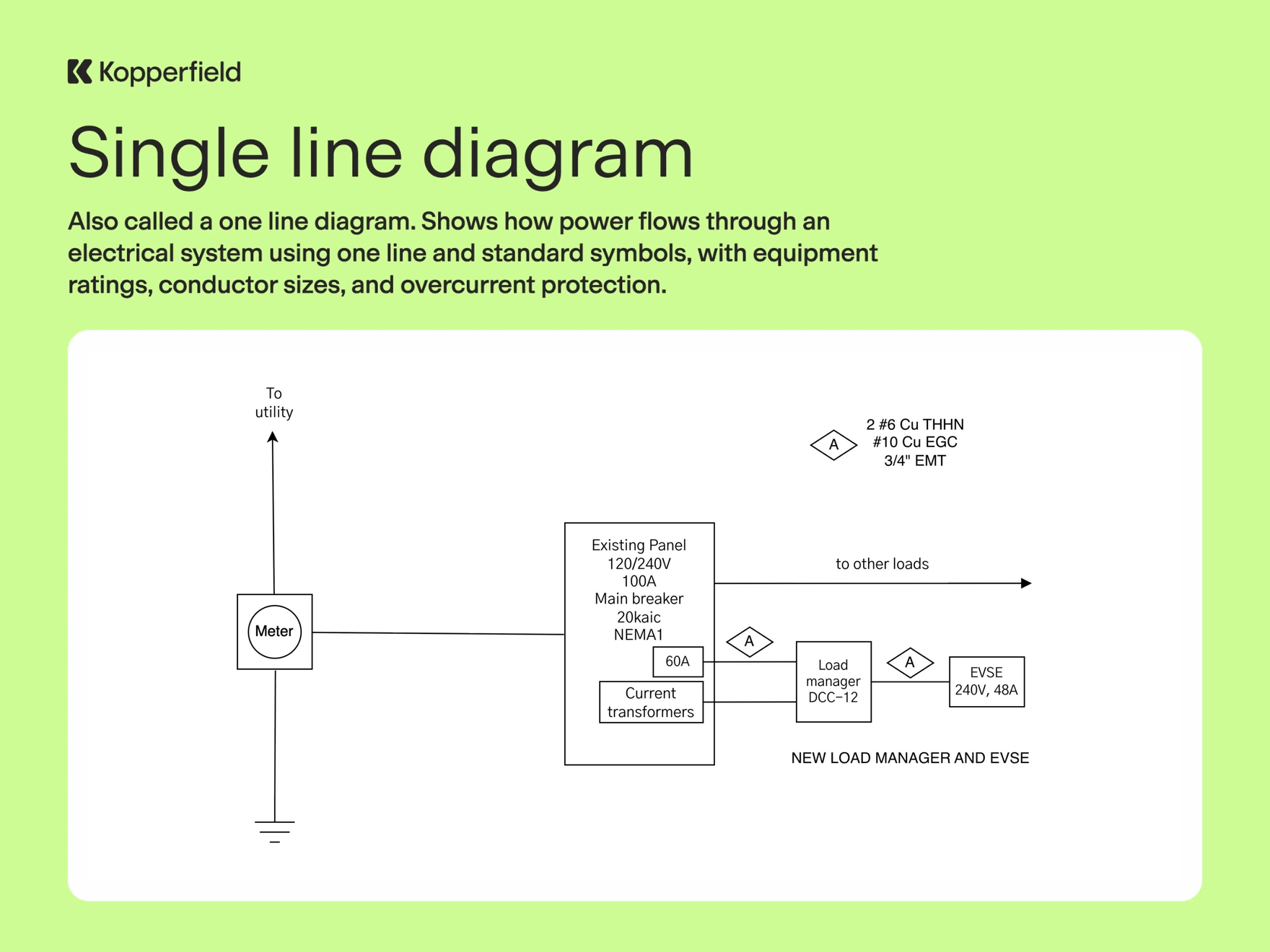
A 48A EV charger added to an existing 100A panel through a load manager. The panel carries its voltage, ampere, interrupting, and enclosure ratings, the branch circuit its breaker and conductor callout, and the drawing marks what is new.
A single line diagram makes it clear how the electrical system will work. It shows power moving from the utility service through the equipment to the loads, typically with standard symbols, using one line even when the circuit has two, three, or four conductors. Single line diagram and one line diagram mean the same thing.
The format works because it strips out detail nobody needs at the planning and permitting stage. A plan reviewer doesn't need every conductor drawn separately to confirm that a 200A service can feed a new subpanel and an EV charger. They need the ratings, the sizes, and the order of equipment.
A single line diagram usually includes:
- Service equipment and panelboards with ampere and voltage ratings
- Feeder and branch conductor sizes, types, and conduit sizes
- Overcurrent device ratings
- Grounding electrode system
- Clear marking of new vs. existing equipment
Requirements vary by AHJ. Electricians commonly create single line diagrams for service and main panel additions, subpanel additions, and EV charger installations. Check what your jurisdiction expects before you draw.
A single line diagram is different from a three line diagram, which draws every phase conductor separately. Three line diagrams are used on commercial and industrial jobs where connection detail matters, like CT metering and relay protection, while the single line diagram covers the system overview a permit reviewer needs.
2. Riser diagram
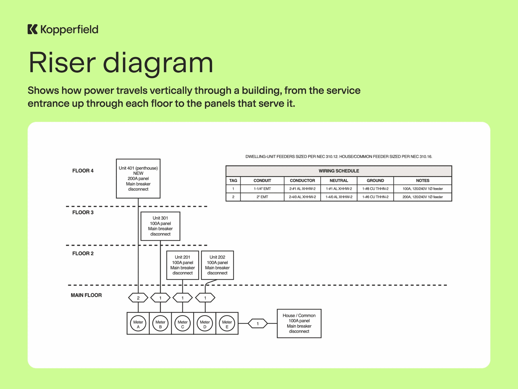
A four-unit building metered on the main floor, with a house panel for common loads. Each feeder carries a tag keyed to the wiring schedule, and the new penthouse unit is marked NEW.
A riser diagram is a single line diagram arranged by location. Traditionally it shows power travelling vertically, from the service entrance up through each floor to the panels that serve it, with feeders, panel locations, and distribution equipment called out; in the field the same name covers layouts by wing, zone, or building. It's common on multi-story commercial and multifamily projects. Kopperfield supports riser diagrams in the same editor used for single line diagrams.
Electrical riser diagrams covers the drawing in depth, including when your AHJ requires one, the symbols that turn up on it, and why risers get rejected in plan review.
3. Wiring diagram
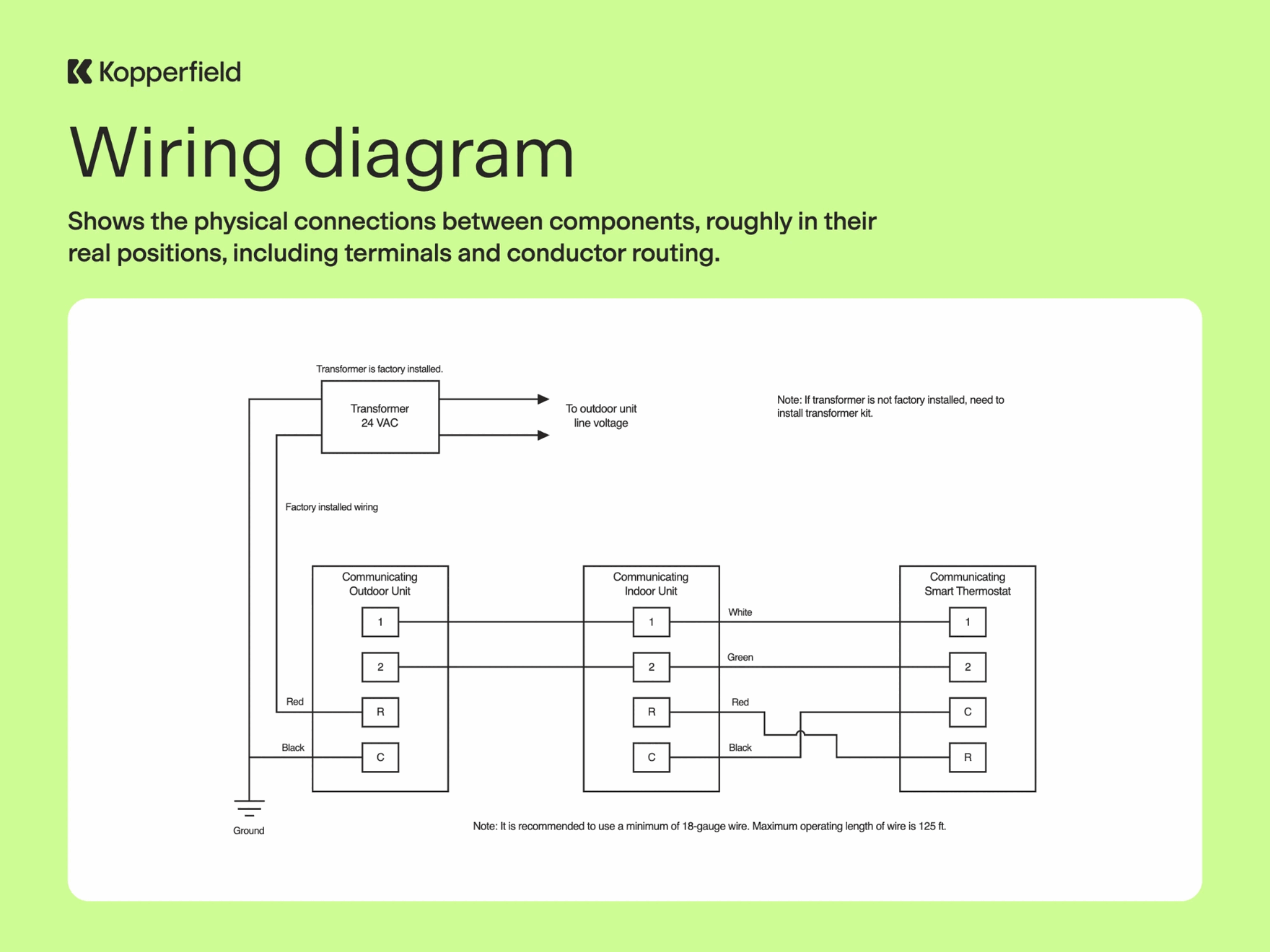
A communicating HVAC system wired to a smart thermostat. Every conductor is traced to the terminal it lands on, with wire colors called out and the factory-installed 24 VAC transformer shown above.
A wiring diagram shows the physical connections between components, roughly in their real positions, including terminals and conductor routing. It's the drawing you work from when installing or hooking up equipment, and manufacturers include one in most installation manuals.
The term wiring diagram is sometimes used loosely for any electrical drawing, but it refers specifically to a drawing of physical connections.
4. Schematic diagram
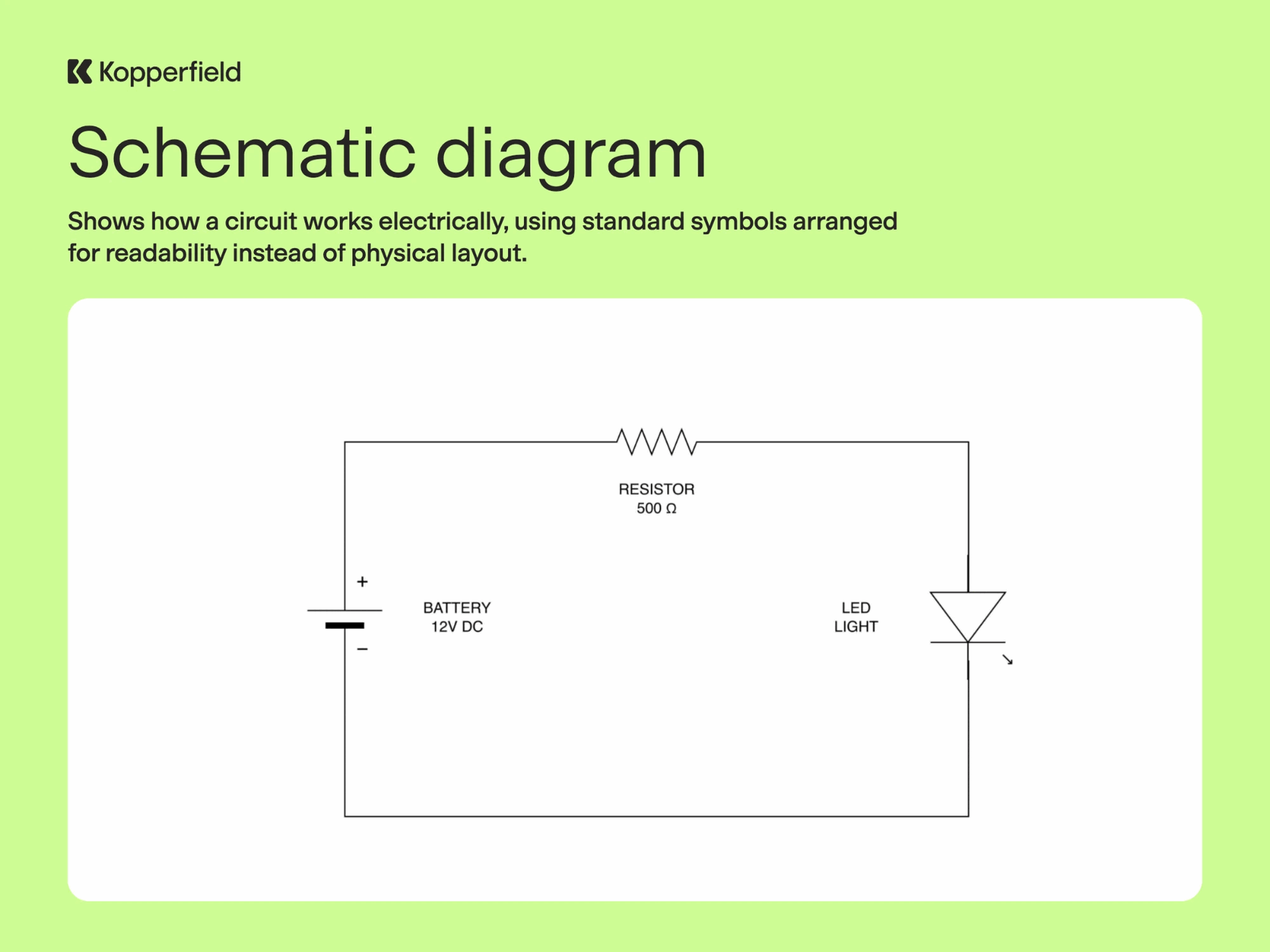
A 12 V battery, a 500 ohm resistor, and an LED in series, drawn with standard symbols.
A schematic diagram shows how a circuit works electrically, typically with standard symbols. Components are placed where they make the circuit's operation easy to follow, not where they sit in the panel or enclosure.
5. Pictorial diagram
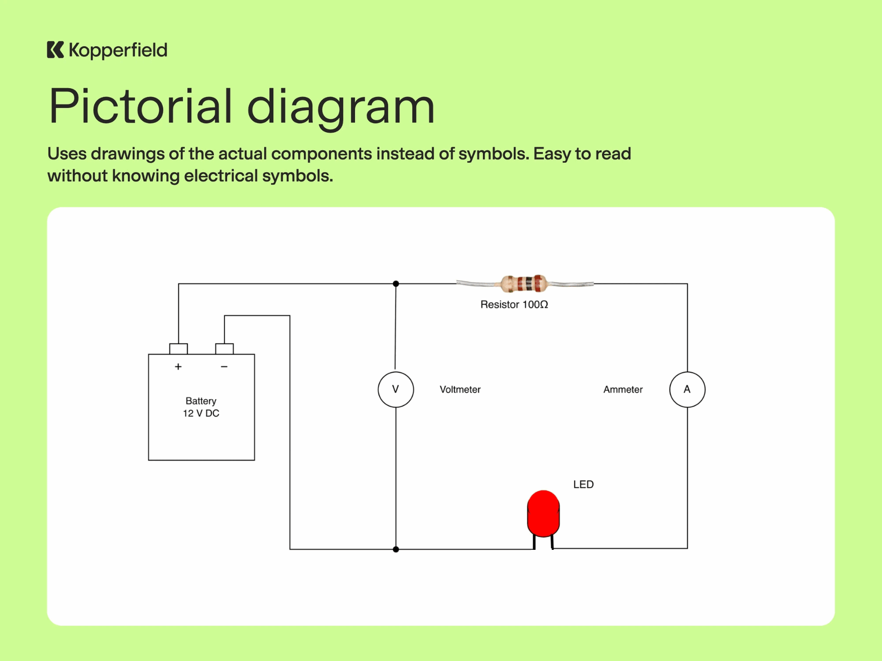
A 12 V battery, a 100 ohm resistor, and an LED, drawn as the components themselves, with a voltmeter across the battery and an ammeter in series.
A pictorial diagram lays out the components and the wiring between them, labeled so the drawing can be read without knowing the symbol set. Some include drawings or photos of the actual components. That makes the format useful for training and for walking a homeowner through the scope of work.
6. Block diagram
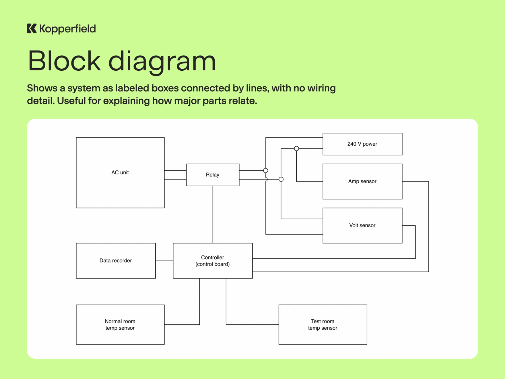
An air conditioning test rig as labeled boxes: controller, relay, amp and volt sensors, room temperature sensors, and a data recorder.
A block diagram shows a system as labeled boxes connected by lines, with no wiring detail. It explains how major parts relate, like a PV system's array, inverter, battery, and service panel, before anyone gets into conductor sizes or terminations.
7. Floor plan
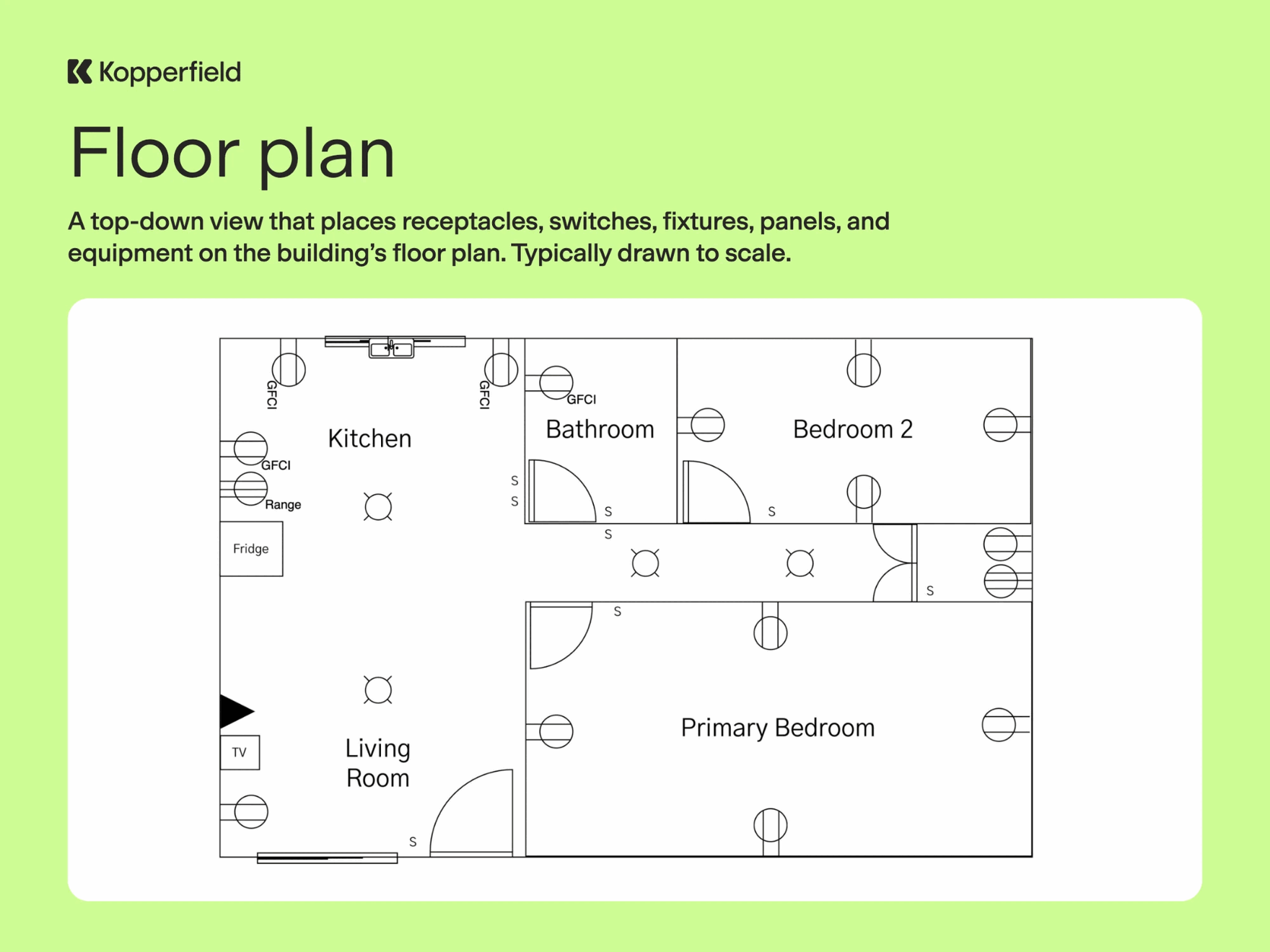
Devices placed on a single-family floor plan, with GFCI receptacles marked in the kitchen and bathroom and a dedicated range receptacle.
An electrical floor plan, sometimes called a layout drawing, is a top-down view of one floor, generally drawn to scale. It places receptacles, switches, fixtures, panels, and equipment on the building's floor plan, often with circuit numbers and home runs. It tells the crew where everything goes during rough-in.
On many jobs it is paired with a single line diagram and a panel schedule, which lists every circuit, breaker size, and load in each panel. Panel schedules are not covered in depth here.
8. Site plan

A minimal site markup: the callout gives the charger rating and how it mounts, the arrow ties it to the spot on the property, and the north arrow sets orientation. A permit-grade site plan adds property lines, a scale, and the route from the panel to the charger.
A site plan is a top-down view of the whole property, not just the building, and is generally drawn to scale. Where a floor plan stops at the walls, a site plan shows the lot: property lines, building footprints, driveways, and how everything sits relative to the street. It is also called a plot plan. It usually includes a north arrow or other cardinal direction so the orientation is not in question.
On an electrical site plan, the detail that matters is everything outside the building, and everything between the building and the utility.
A site plan usually includes:
- Property lines and building footprints on the lot
- Where the service enters the property, overhead or underground
- Meter, main disconnect, and panel locations
- Underground raceway and feeder routes across the lot
- Outdoor equipment locations: EV chargers, solar, batteries, generators
- Detached structures on their own feeders, such as garages, shops, and ADUs
- Clear marking of new vs. existing work
Scale does real work on this sheet. A feeder run that looks short on paper can be a long pull across a lot, and length drives conductor size and voltage drop. Measuring the run off a scaled drawing is faster than pacing the lot twice.
Site plans earn their keep when the work covers more than one structure, or equipment sited away from the building. That covers most EV charger, solar, battery, and ADU work.
9. Scope of work drawing
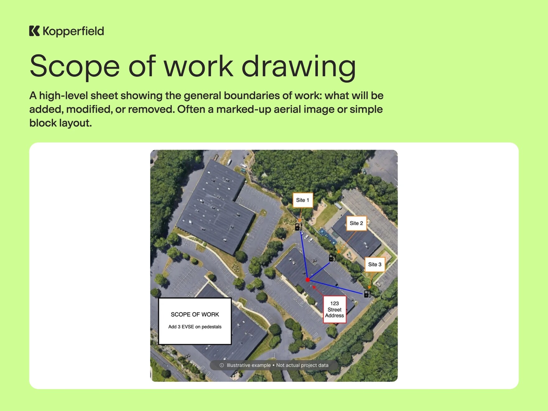
Three new EV charger sites marked on an aerial image of the property, showing which building feeds them and roughly how the runs get there.
A scope of work drawing, sometimes labeled a scope of work map or carried on a key or index plan, is a high-level sheet showing the general boundaries of the work: what is being modified, what is being removed, and what is being added. It carries no fine technical detail.
It can be a line or block diagram, or a marked-up satellite image of the property. The job of the sheet is to set the limits of the work so the owner, the GC, and the AHJ are reading the same thing.
An index sheet with a plot plan is a related document. It is usually a cover sheet with a bird's-eye view that marks the zones of change along with site and client context.
Which electrical diagrams do you need for a permit?
For residential permits that need drawings, such as service upgrades, subpanels, EV chargers, and solar or battery installs, the core documents are a single line diagram and a load calculation, often with a panel schedule and a site plan. Commercial permits typically add electrical floor plans, riser diagrams for multi-story buildings, and available fault current documentation. Your AHJ will determine which diagrams you need for the project. Check with them early.
What symbols are used in electrical diagrams?
There's no universal or required set of electrical diagram symbols. Schematics and single line diagrams in the US generally follow IEEE Std 315 (also published as ANSI Y32.2), which is no longer actively maintained, and construction drawings like floor plans follow ANSI/NECA 100. Conventions still vary between engineers, plan reviewers, and jurisdictions. What matters is that the plan reviewer can read your diagram.
To keep a diagram easy for a plan reviewer to follow:
- Add equipment labels as needed
- Use a legend whenever symbols are used
- Keep symbol usage consistent across every sheet in the set
Draw your next single line diagram in Kopperfield
Kopperfield's single line diagram tool gives you standard electrical symbols and a free PDF you can attach to your permit application. You can upload an existing plan set to add redlines or inspector comments, and draw from the Kopperfield app on iOS and Android tablets.
👉 Draw a single line diagram in Kopperfield
Frequently asked questions
What are the different types of electrical diagrams?
The ones that come up most are single line (or one line), riser, and wiring diagrams. Between them they cover how power is distributed and where each conductor lands. Schematics, pictorial diagrams, and block diagrams explain how a circuit or a system works. Floor plans, site plans, and scope of work drawings show where everything goes and how far the job extends.
How many types of electrical diagrams are there?
There is no agreed number. Trade training usually teaches four basic types: schematic, wiring, block, and pictorial. Contractor lists run longer, because they follow what the job and the AHJ need rather than a fixed list.
Which electrical diagram is used for troubleshooting?
Usually the schematic and the wiring diagram together. The schematic shows what the circuit should be doing, and the wiring diagram shows where each conductor lands, so you know where to put the meter. For a distribution problem in a building, start from the single line or riser diagram to see what feeds what. Whichever you reach for, an out-of-date drawing is worth far less than an accurate one.
Which electrical diagram shows where components are physically located?
Wiring diagrams show components roughly in their real positions, down to terminals. Electrical floor plans show where devices, fixtures, and panels go in the building. Single line diagrams and schematics don't show physical location.
What's the difference between a wiring diagram and a schematic?
A wiring diagram shows where components physically are and how they're connected. A schematic shows how the circuit works, regardless of physical location. When something isn't working, the schematic tells you what should be happening, and the wiring diagram tells you where to put your meter.
Is a one line diagram the same as a single line diagram?
Yes. One line diagram and single line diagram are two names for the same drawing. Both show a power system using a single line to represent each circuit's conductors.
What's the difference between a single line and a three line diagram?
A single line diagram represents all conductors of a circuit with one line. A three line diagram draws each phase conductor separately and is used where connection detail matters, like metering and relay protection.
Can I make a single line diagram for free?
Yes. Your first two single line diagrams are free with a free Kopperfield account, no credit card needed, and the PDF export for the permit set is included. Further diagrams need a paid plan.